BIM Import & Modeling Guidelines
Model considerations
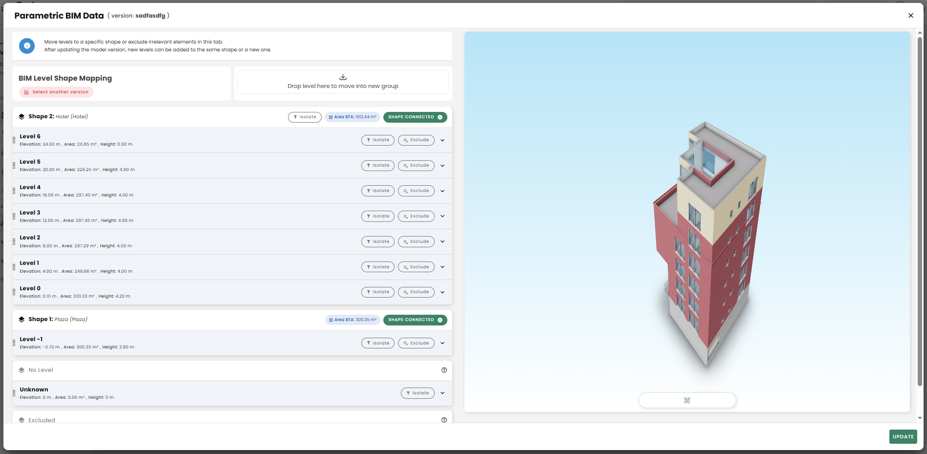
Dividing a Building by its Functions/Shapes in Reduzer
Reduzer organizes elements from Revit or ArchiCAD models into groups based on their building level. This allows the user to assign a specific building function (typology) to each level, which in turn isolates the energy consumption requirements for that function.
🍀 TIP
Right now, you can only assign one function to an entire floor.
If you need a single level to have multiple functions, you'll have to work around this by modeling all areas on that floor as one single, combined shape.
Element Categorization - Parameters
🍀 TIP
Estabilish categorisation
It's important to categorize all modeled objects correctly from the very beginning of a project.
Doing this in the early stages helps avoid having to redo work later. If you don't establish proper categories early on, updating the model in later phases can become unnecessarily complex and inefficient.
Categorization in...
Revit
| Element | Required Parameters | Notes |
|---|---|---|
| Walls, Slabs | Function (Walls), Structural (checkbox)1 | e.g., Exterior, Interior; Structural |
| Curtain Wall Panels | Use custom Curtain Panel families where needed 2 | Include shared parameters like and naming PanelFunction, InsulationCode, Panel_900x2100_Wood |
| Doors, Windows | Function, Type Mark, Comments | Use naming format: Door_900x2100_Wood_Int |
| Generic Models | Avoid or re-categorize to correct system family | Custom parameters will be extra data. |
| Model-In-Place | Avoid if possible; assign correct category/tag |
1 Not checking this box will assign the element as Non-Structural
2 Suggestion -Make an explicit decision and guideline for your team -Two options:
- Create custom Curtain Panel families (loadable families using the Curtain Panel template)
→ Add shared parameters like Function, InsulationType, etc.
→ Allows full control but requires family creation.
- Keep system panels but apply taggable shared parameters using instance-based parameters or key schedules linked to panels (via panel type or host wall).
ArchiCAD
| Element | Required Parameters | Notes |
|---|---|---|
| Walls, Slabs, Beams | Structural Function, Position | LoadBearing/NonLoadBearing + Interior/Exterior |
| Curtain Wall Panels | Position | Manually tag if needed |
| Morphs, Objects | Assign to proper Layer and Classification | |
| Doors, Windows | ID, Position | Use format: Window_1200x1500_Alum_Ext |
- Libraries should be properly categorized if they weren't by the company or if it doesn't adjust to the model criteria.
LAYERING SYSTEM: For Norway the SIMBA – Statsbygg’s BIM Manual should be followed.
Since BIM guidelines differ significantly across countries and projects, it is recommended that international BIM files use a standardized ArchiCAD Layer System. This, for example, could include most of the default ArchiCAD classification layers, with specific exceptions for elements modeled using WALL and SLAB tools:
For WALL-based elements, create additional layers that categorize them based on their Position (e.g., external or internal) and Structural function (e.g., load-bearing or non-load-bearing). Similarly, for SLAB-based elements, distinct layers are required to differentiate various horizontal components such as suspended ceilings, shading devices, roofs, flooring, and other finishes.
PARAMETER ORGANIZATION: Ensure that elements have the correct parameters. In addition to the ArchiCAD Layer name, the material composition, Element ID, and Renovation status parameters are extracted. These fields may retain their default values, depending on the current project stage (e.g., Concept, Preliminary Design..).
Depending on the maturity of the model this data can be used as reference to organize the data once in Reduzer.
If the model is intended for early design calculations, this “data categorization” can be missing as long as there is a clear and general acknowledgement of the proposed materials for the walls, roof, etc. As the model develops with more categorization parameters, elements can be reorganized automatically once in Reduzer.
Speckle Connection
Connectors publish models to Speckle without relying on files—every piece of geometry or metadata is extracted and uploaded. Once the models are published to Speckle, they are stored securely in the cloud.
WARNING
Currently there is no support from models sent via Version 3. Use Speckle manager instead (), available here: Version 2 - legacy
The new generation of connectors will replace the current ones (version 2). The new Connectors (version 3) are now set as the official connectors on the website. They can be directly downloaded individually from this page: V3 Connectors.
Download Speckle
Go to SPECKLE and create a User Account
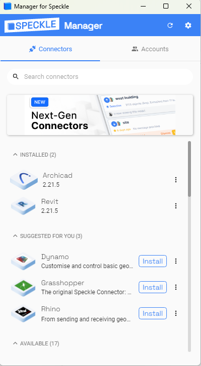
Download Speckle Manager
Close your BIM authoring tool, before installing or updating the plug-in.
Download the desired plugin from the Speckle Manager app. Updates to the connector can be performed here as well.
Upload your model
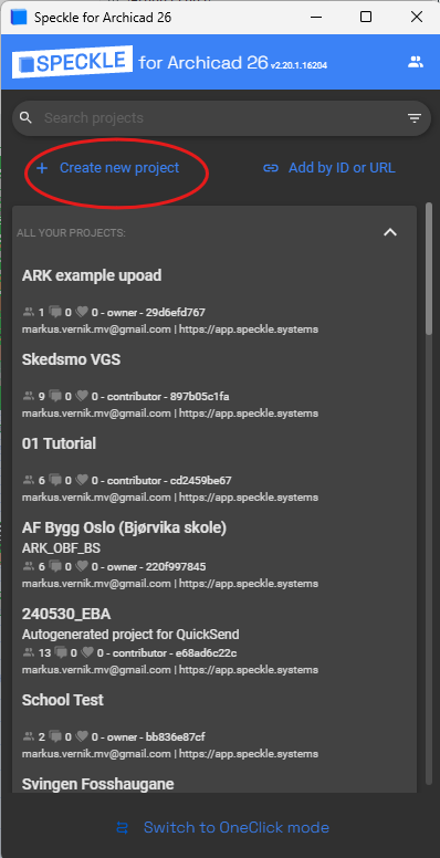
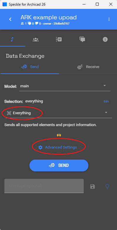
Quick Speckle upload
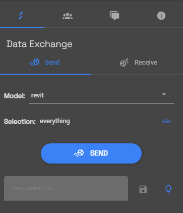
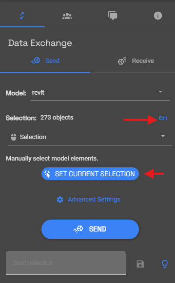
Ensure you select only relevant elements for your calculations.
Selecting “Everything” in the Speckle tab will include hidden objects that might not be useful (example context geometry, landscape, etc). To avoid this click on Edit -> Selection-> Set current selection
It's important to update the selection via clicking on Set current selection each time something is added or excluded, prior to sending your model.
Advanced Upload Options
WARNING
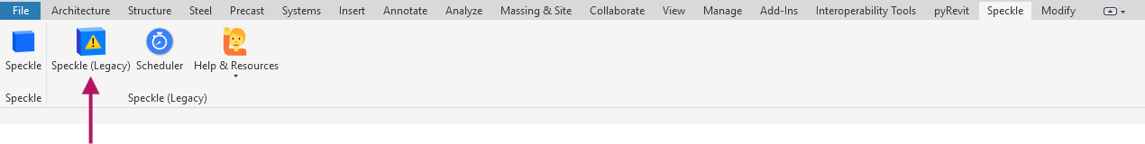
Instead of Speckle (connector version 3 is not supported), use Speckle Legacy (version 2)
Advanced Upload in...
Revit
- Open Speckle in Revit through the following route: Main Ribbon -> Speckle -> Revit connector.
- Switch to “Advanced mode” once the window is opened.
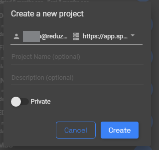
- Create a new project with the default privacy settings (untoggled)
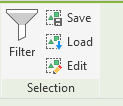
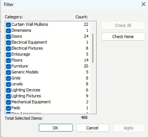
- Use the Filter tool to exclude categories if needed.
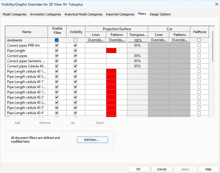
5. Alternatively or simultaneously configure filters in the view to hide irrelevant building parts.
ArchiCAD
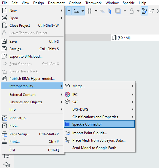
Open Speckle in ArchiCAD through the following route: File tab -> Interoperability -> Speckle connector.
Switch to “Advanced mode” once the window is opened.
Create a new project with the default privacy settings. (untoggled)
Ensure you select the relevant elements for the calculations.
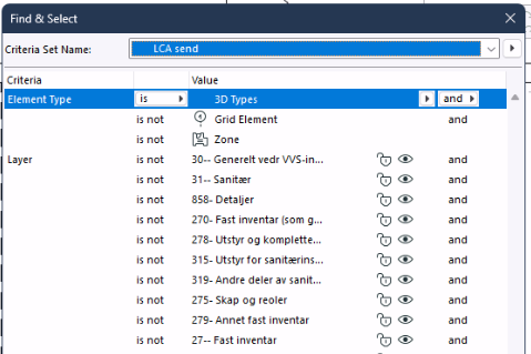
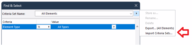
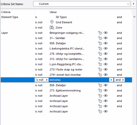
Use Find & Select tool, to exclude elements before sending.
Grids and other elements not relevant should be excluded.
Criteria Sets can be saved and exported across projects as .xml
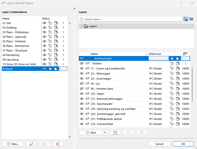
Alternatively or simultaneously Layer combinations can be used to exclude elements with a preset criteria.
- Selecting with Left click -> Box selection can work if the layer combination is set to hide those elements that are not relevant in advance.
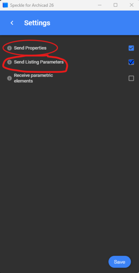
Before sending, go to "Advanced settings" in the Speckle window and choose "Send Properties." and “Send listing parameters” This will include additional information such as the layer system, renovation phase, and wall composites.
To open Speckle plug-in go to File -> Interoperability -> Speckle connector
Share and review the model
Share your Speckle project:
Go to Collaborators → Invite (Assign the invited people collaborator roles)
- Invite to project:
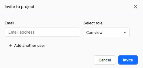
- Navigate to Collaborators:
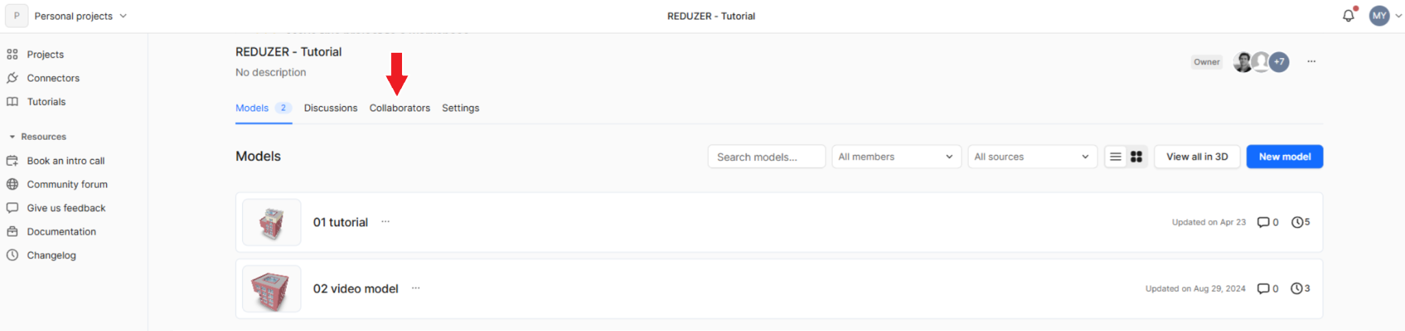
- Choose 'Invite to project':
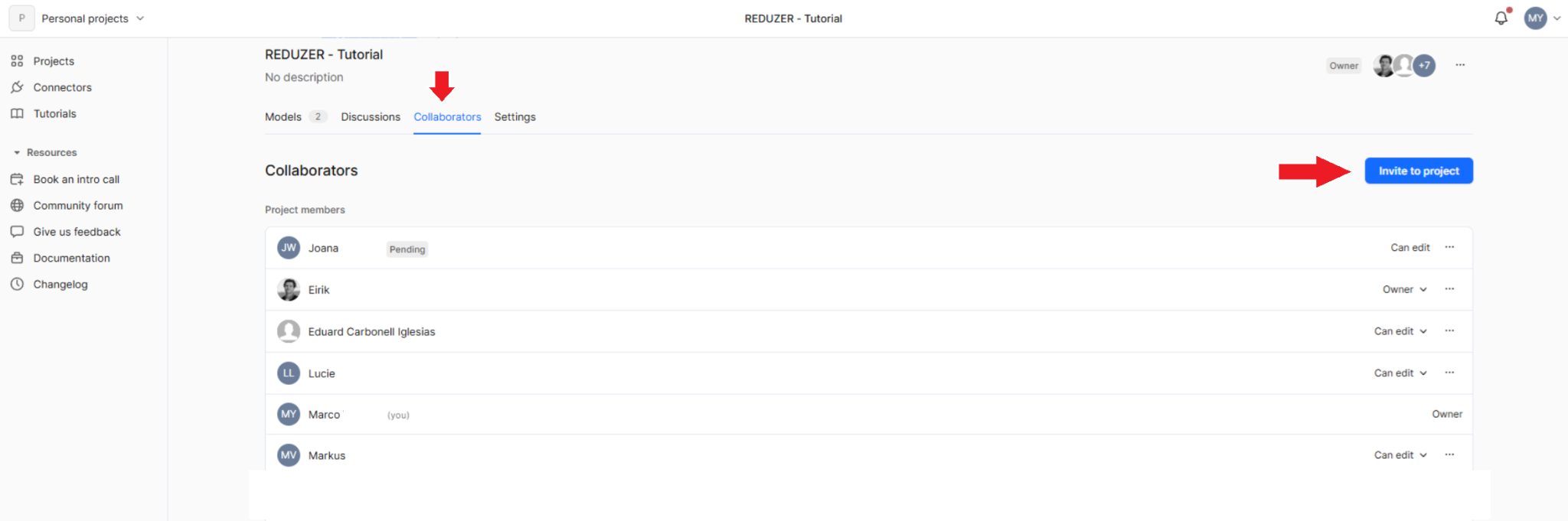
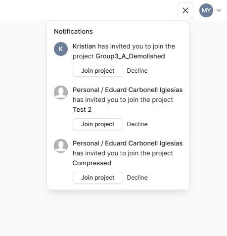
- The invited person needs to accept invitation!
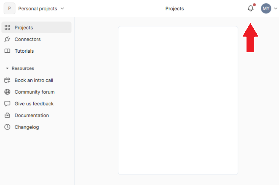
- It can be found in the notifications tab:
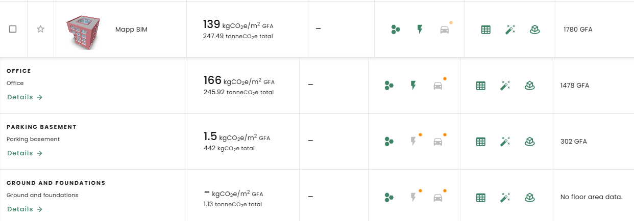
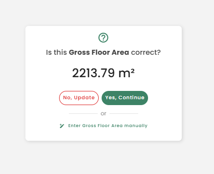
Automatic Gross Floor Area Calculation
Reduzer automatically includes any building element modeled with the Floor/Slab tool in the Gross Floor Area (GFA) calculation. This means every element modeled in this way, such as: structural slabs, screeds, and flooring layers, detailed elements, etc… If there are several superposed objects all of them will be accounted for.
If a flat roof is modeled using the Floor/Slab tool, it will be included in the GFA. However, if the same element is modeled using the Roof tool, it will not be counted in the GFA.
🍀 TIP
The automatic GFA calculation is intended for early-stage design models. As your model becomes more detailed, you can refine the GFA in Reduzer by excluding certain elements from the count or manually entering the correct area values.
Therefore users don’t need to change your BIM model to correct the GFA.
This provides the user with full control over GFA estimation without having to remodel anything.
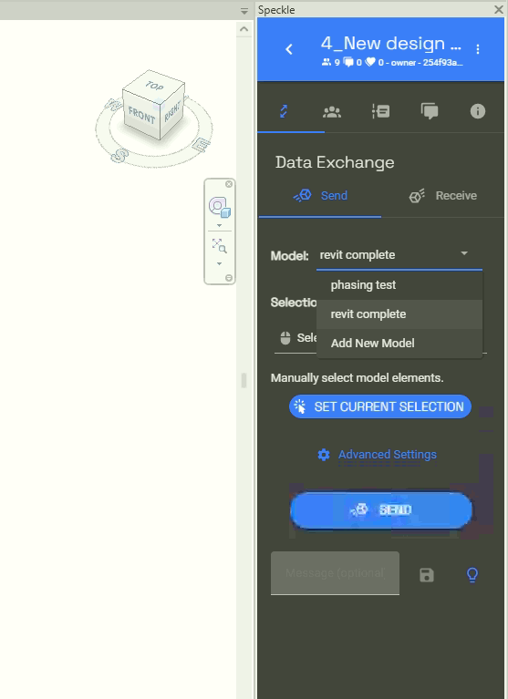
Manage Several Models
Speckle lets you keep several different models within the same project.
This is especially useful when a project is still developing and you need to evaluate and compare different design ideas.
Here's an example:
An early design phase featuring a model with several alternatives, can be assessed with the Design Options function. To send this information, a dedicated preset view is required. Alternatively such elements need to be selected within the design option > exit design option > select previous> Ctrl + select the whole building > Send (data to Speckle)
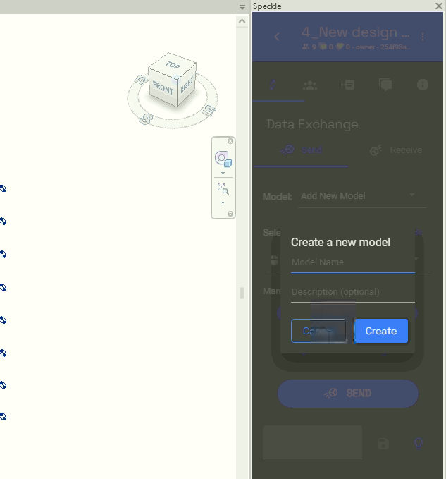
Select the saved Speckle project > Create New model > Add a name and description to the new model branch> Selection > Set current selection (or View, whichever is convenient)> Send
- This process creates an independent Model Branch, allowing to differentiate design options. Each branch can be updated as many times as needed.
A. To update one of such alternatives, make sure that the Model Branch is correctly selected before uploading into Speckle.
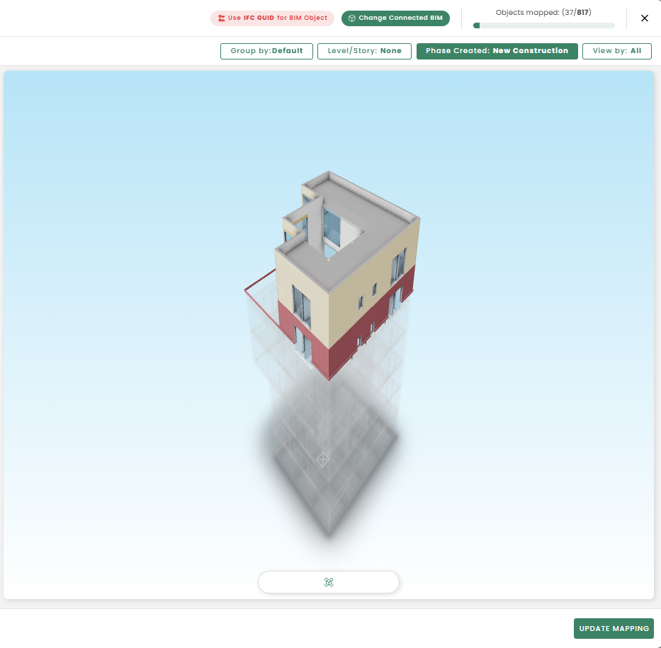
B. Any changes on the model are reflected on Reduzer BIM update mapping by tracking the elements GUID.
- Sending models from multiple disciplines (Architectural, HVAC, Engineering ) has the same workflow as the multiple design alternatives - Selecting the saved Speckle project > Create New model > Adding a name and description to the new model branch> Selection > Set current selection (or View, whichever is convenient)> Send
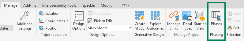
Manage Phases
If the project involves refurbishment, make sure to adjust the Phases in Revit or the Renovation Status in Archicad. Using these features allows for more accurate tracking of data based on complex criteria, such as demolished elements or any other phase-specific conditions.
🍀 TIP
Each software provides similar tools for handling renovation and project lifecycle stages, but differ in workflows integration, flexibility, and user control. Some considerations for each feature are listed as follows:
| ArchiCAD | Revit | |
|---|---|---|
| Phases | 3-state intuitive system | More complex, but highly flexible. |
| Purpose | Control visibility and graphical representation of existing, demolished, and new elements. | Define project stages (e.g., existing, demolition, new construction) and manage changes across time. |
| System Type | Attribute-based (elements have a renovation status). | Phase-based (elements belong to a specific project phase). |
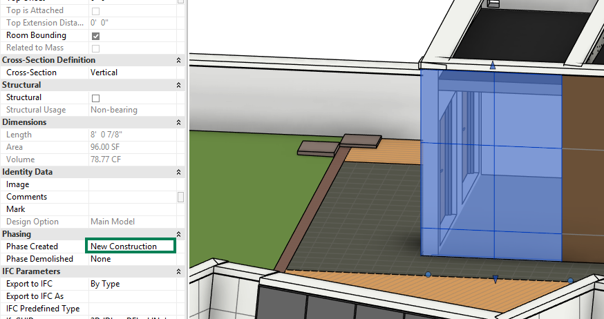
| Element Handling | One status per element: Existing, To Be Demolished, New. | Each element is assigned a "Phase Created" and optionally a "Phase Demolished". |
| Custom Phases | Limited to 3 states (though filters can be customized). | Unlimited phases, allowing highly detailed phasing (e.g., multiple construction stages). |
| Element Lifecycle | Not well suited to projects with more than 3 stages. | Designed to handle multi-phase projects (e.g., phased construction, renovations over years). |
Manage Phases in...
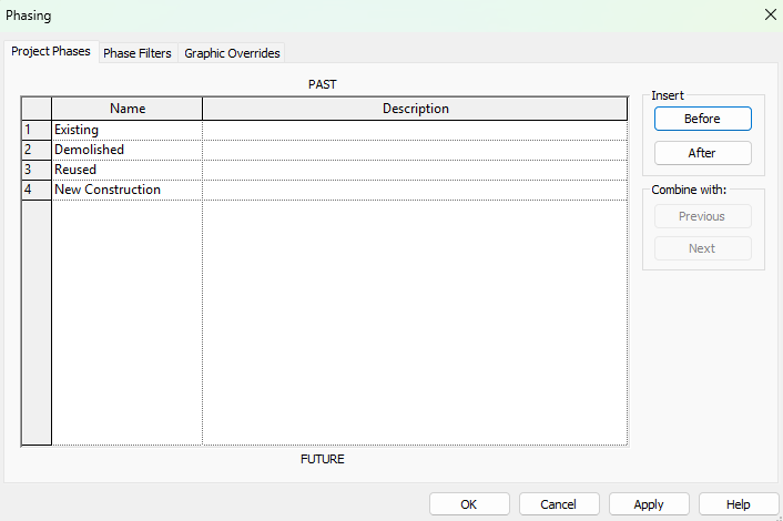
Revit
Managing views and phase filters can become hefty without proper organization, it requires careful handling of visibility control when modeling.
Each element in the model will be assigned to a phase depending on the phase of the view.
ArchiCAD
Limited to 3 renovation statuses it’s less suited for complex, multi-stage phasing.
However, there are several workarounds that can be applied to simulate these modes. For example use custom Renovation Filters + Layer Combinations to represent multiple construction phases, Element Classification or Custom Properties (IFC/Expressions), use Hotlinked Modules per Phase, among others.
Send to Speckle in...
Revit
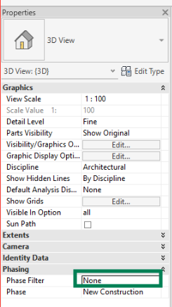
- When exporting the model to Speckle the Phasing filter in Revit view should be set as None or Show All Elements, which will reveal all of the phases in that view, once in Reduzer it can be filtered, organized and mapped by phase. This approach is suited if users wish to have all elements in the same model.
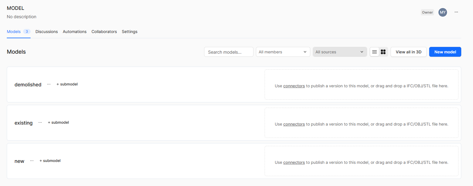
Alternatively different model branches in Speckle can be created for each phase. Before sending each model into Speckle:
The phasing filter should be set as Show Complete, in a preset View that represents New, Existing, Demolished phase, etc. respectively.
ArchiCAD
- When exporting the model to Speckle, set Show All Elements in ArchiCAD’s Renovation filter, which will reveal all of the phases in that view. Once in Reduzer it can be filtered, organized and mapped by phase. This approach is suited if users wish to have all elements in the same model.
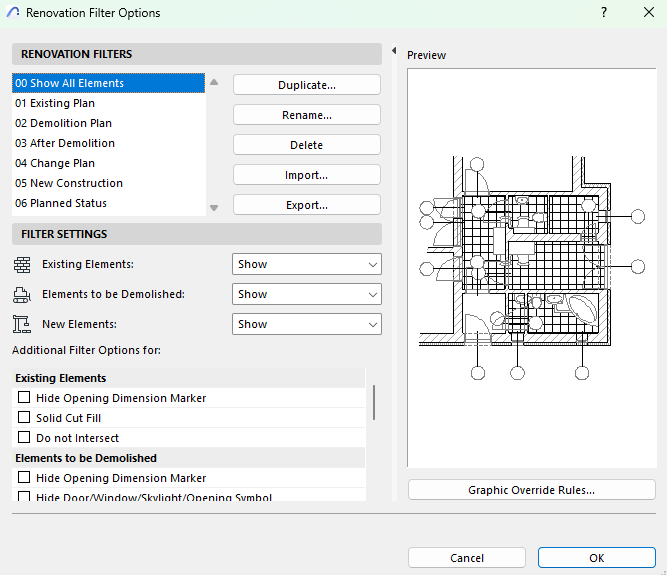
Alternatively different model branches in Speckle can be created for each phase. Before sending each model into Speckle:
Phasing filters should be configured per Renovation status or alternative organization workflow.
IFC export to Reduzer
In this section we brake down workflow for IFC export. Choose the program you want to work with:
BIM mapping explained
A step by step tutorial video where you can learn how to map your BIM model once you uploaded it in Reduzer.
Phases in IFC
For phasing workflows with IFC it is not possible to export demolished elements, and each phase has to be exported separately. Speckle exports work smoother with this functionality.
IFC in...
Revit
Create a unique dedicated View in your Revit model to perform IFC exports
Use and configure filters in the View to hide irrelevant building parts before editing the IFC export settings.
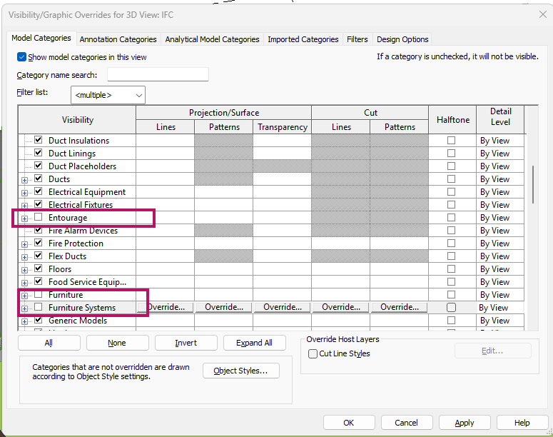
Excluding Furniture and Entourage Revit categories, these elements are normally not accounted for in LCA.
Other examples are context geometry, placeholder geometry, landscape, etc.
Some structural detailed pieces should be excluded. According to European standard
Create an Export template
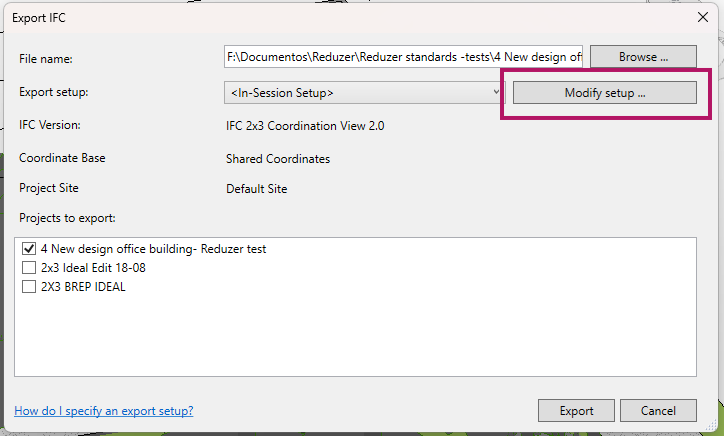
Additionally Category Mapping settings can be adjusted in order to avoid elements being classified as IFC Building Element Proxies.
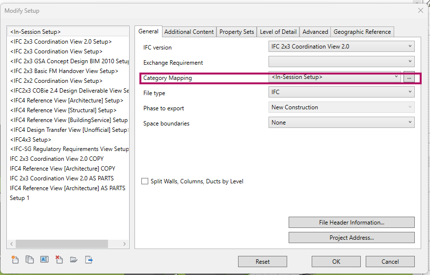
- This causes modeled elements to be badly categorized in IFCclass, such adjustments should be project specific since modeling requirements for different elements vary from project to project.
In other words this means creating elements using inappropriate model categories (e.g: terrain as a slab, stairs as a beam). Regardless of this setting, the file can still be used, but it is harder to find and understand elements while mapping if many have mismatched categories.
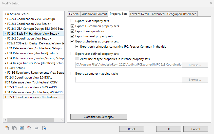
Property sets tab has to include base quantities and IFC common property sets
- Additionally using -user defined property sets- can include other relevant information that does not usually come in the IFC schema.
For example:
I. MMI (Model Maturity Index)
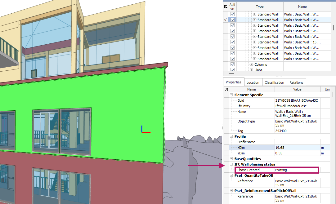
II. Information of Phasing status (when the object was created)
III. Place/Area in the building
IV. etc..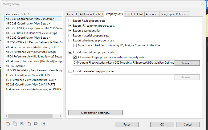
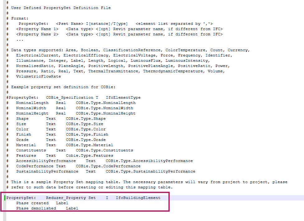
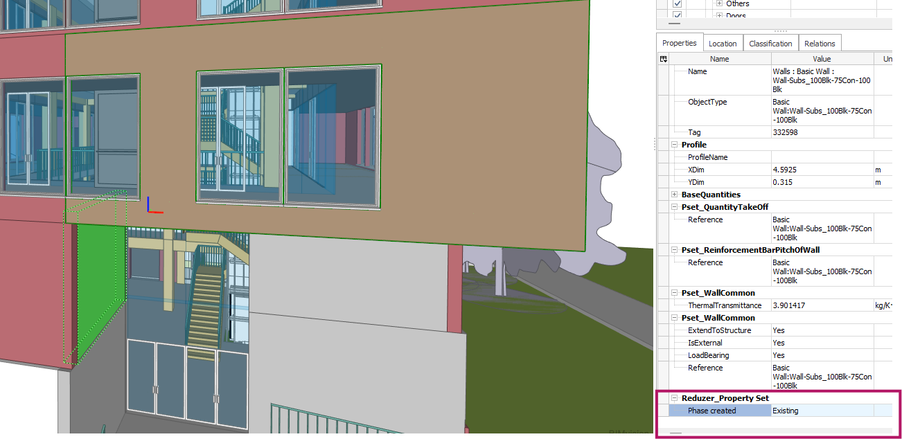
This approach is the best alternative to export specific data in a clean manner and more control. As an example the following txt. The template file will add Revit phases to the schema.
NOTE: Parameters that have no value will not be exported
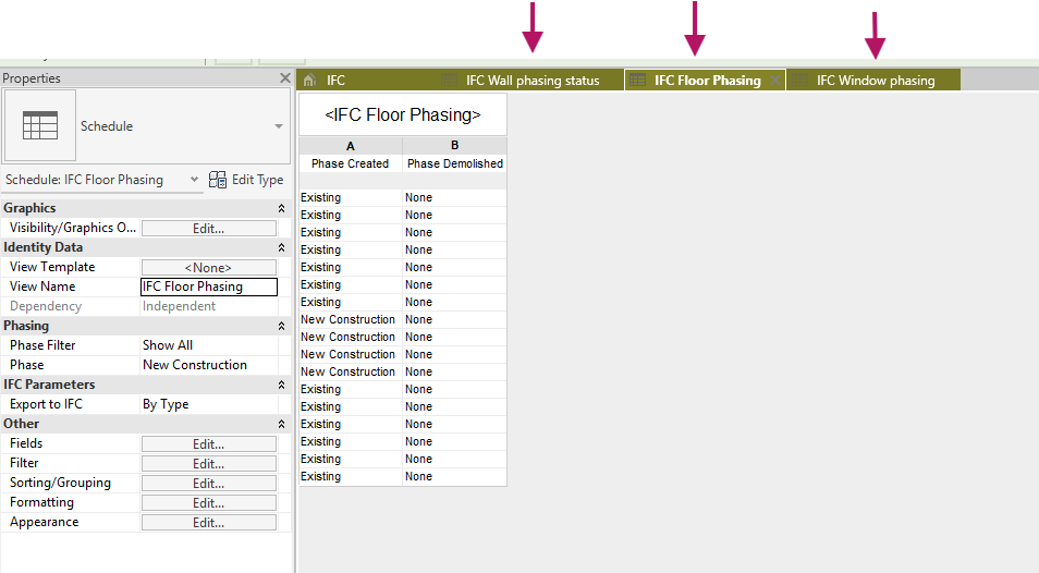
- Alternatively you can create schedules in Revit containing those parameters that are necessary to include in the IFC schema. This workflow is flexible, but vulnerable since schedules can be accidentally modified or deleted. Plus schedules can not be easily transferred among various Revit models.
To illustrate this workflow, the following example includes the phasing status of some Revit categories:
In Advanced settings toggle the following boxes, this will add data required by Reduzer
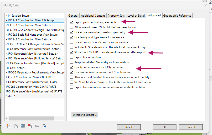
- It is recommended to create a separate IFC file specifically for LCA calculations if the current IFC exports are used for coordination with other disciplines that require other specific IFC export settings.
ArchiCAD
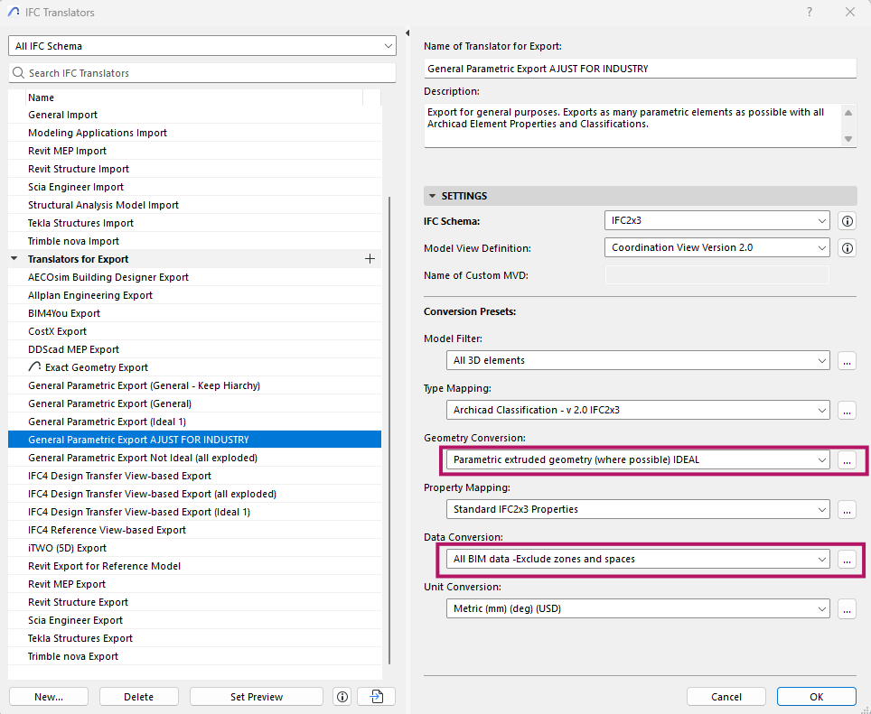
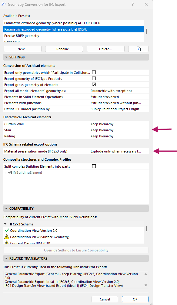
The changes that have to be done are in the Translators for Export, under Geometry Conversion and Data Conversion.
Additionally Type Mapping settings can be adjusted in order to avoid elements being classified as IFC Building Element Proxies. This causes Modeled elements to be badly categorized in IFCclass, such adjustments should be project specific since modeling requirements for different elements vary from project to project. In other words this means creating elements using inappropriate model categories (e.g: terrain as a slab, stairs as a beam). Regardless of this setting, the file can still be used, but it is harder to find and understand elements while mapping if many have mismatched categories.
1. For Geometry conversion the settings that require adjustments are Material presentation mode and Hierarchical Archicad elements
The main goal here is to maintain Composites structures together as one entity
2. For Data conversion add most Quantity ArchiCAD Data to Export (as shown in image) and Derived Data to Export. These are the minimum requirements to display values in IFC 2x3, custom data presets can be added as needed.
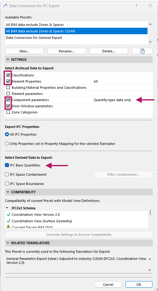
Property Mapping for IFC Export for IFC 2x3 When the export is carried out in this format an additional step is needed. The following process allows to include only relevant data in the export, reducing the file size.
- First open the Property Mapping settings and duplicate the standard template / edit your current template.
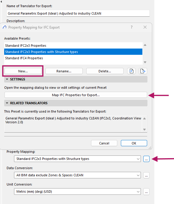
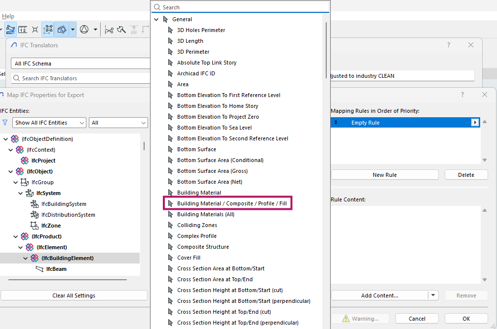
- In the following window we have to create a rule for exporting data. In this case the material relation will be added. Select IFC Building Element to export such property from all elements in the model.
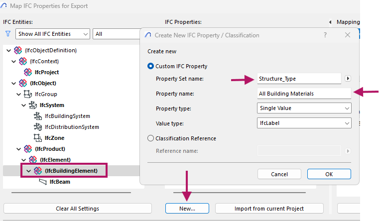
- Create and name a new Property Set, which will be the group where the data will be stored. Then give a name to the property itself - In this case All Building Materials
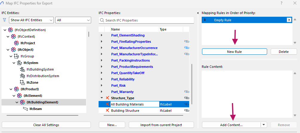
- Now the rule has to be added via New rule → Add content
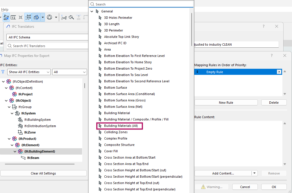
- Search for the property Building Materials (All)
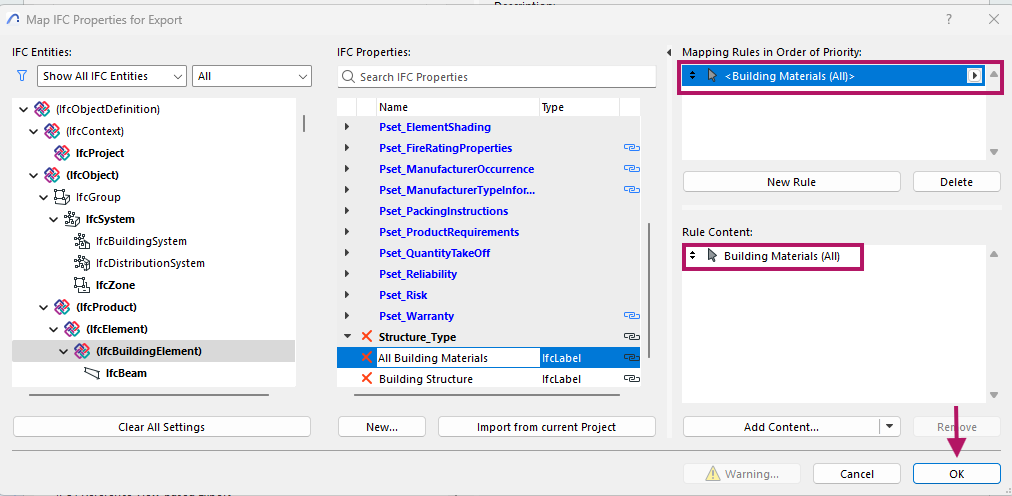
Click OK in the search window and then save.
Repeat this process with a new property grouped in the same Property Set
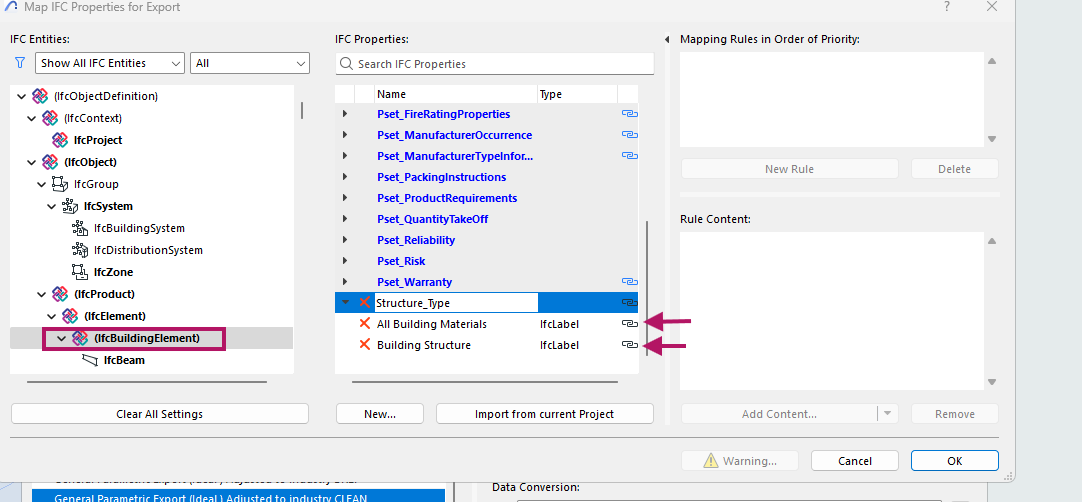
- This new property should have Building Material /Composite / Profile/ Fill
We recommend creating a separate ARK IFC file specifically for LCA calculations if the current ARK IFC export is used for coordination with other disciplines that require other specific IFC export settings.
Labeling and naming system for walls, slabs, roofs
A Flexible Guideline for Your Team
Think of this coding guideline as a starting point that you can adapt to your company's workflow. For it to be effective, everyone—including employees and outside collaborators—needs to use it consistently and understand it. Good documentation is key to making sure everything stays clear and communication is smooth.
The main goal of this structure is to help you not only identify specific elements but also to understand how complete the BIM data is and how far along the design is, especially when running life-cycle assessment (LCA) calculations.
How It Works
By using a consistent naming system for things like walls and slabs, you can immediately get a rough idea of their material composition, even in the early design stages. When creating new building elements, make sure their names are clear and understandable to everyone on the project, following your company's internal naming rules.
It's crucial to maintain clarity and consistency to make tracking data easy. If the naming rules aren't followed, you can make adjustments later in Reduzer, but this creates extra work.
🍀 TIP
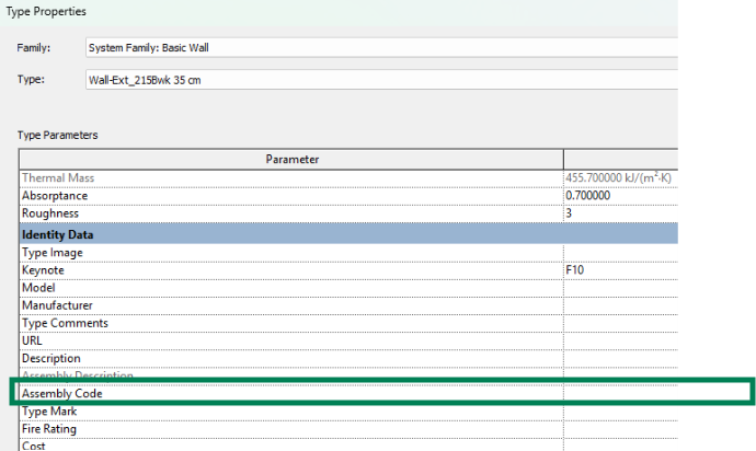
Using Codes for Detailed Data
For more complex projects, you can use a separate label or parameter (like an Assembly Code) to hold the specific material data. This allows the element's name to stay simple and readable, while the code contains the precise technical information. These codes can then be tracked directly inside of Reduzer.
Example Naming System
This is a Sample Code
We created this sample code to show why a clear naming system for your model elements is so important.
Feel free to use our system, but keep in mind that most companies develop their own. Ultimately, you can use any system you prefer, as long as it is consistent, easy for your team to understand, and allows you to map every element correctly.
Walls & Slabs Example Code
(Internal wall, External Wall, Slabs, Roofs...)
  150(75-S45/50-MW)H.N-N.H
  Thickness(Structural_data/Insolation_data)Conform-layers
Overall thickness (Structural thickness and material /
Insolation thickness and type)Layers that conform the wall.
🍀 TIP
This naming should be informative, not extensive. In later stages of the project (as built model) the specific data of the material can be added in the material level not in this name.
Practical examples
- Wall 200mm B35 concrete, no insulation:
200(200-CB35/0)
- 100mm wall, steel CC600, 50mm insulation with no type decided yet, and layers not decided yet.
100(75-S60/50/*)***
* - (Not decided yet)
Walls & Slabs Code Definition
Pre-parenthesis: 150
A number which indicates overall thickness in mm of the wall.
Most common: 100 , 200 , 50 , 250
Parenthesis: 75-S45/50-MW
The first part (before the /) number represents the thickness of the main layer followed (with a - as separation) by the material of this layer, the second (after the /) represents thickness followed (with a - as separation) by material of the insulation (if none 0 will represent that).
S45 for steel substructure CC450. and S60 for steel CC600 W16 for wood class C16, etc.
Insulation, the number defines the thickness in mm between studs, if = 0 then there is no insulation.
The type of insulation follows a code to be determined by the company Ex.
MWR = Mineral Wool Rigid panels
GW = Glass Wool
EPS = Eps Boards
XPS = Xps Boards
etc.
🍀 TIP
Can also be used to indicate double wall arrangement, with a double parenthesis:
200mm wall
(75mm steel CC450 / 50mm Mineral Wool Insulation)
(and again 75mm steel CC450 / 50mm Mineral Wool Insulation)
Finished off with one Gypsum Plate Normal and a Gypsum Plate Habito on each side.
200(75-S45/50-MW)(75-S45/50-MW)H.N-N.H
Post Parenthesis: H.N-N.H
Layers that conform to the building part, can be represented by letters, the order explains which layers go on each side. To separate the layers we use a dot in case. (H: Gypsum Habito and N: Gypsum Normal)
H = Gypsum Habito
0 = Nothing
N = Gypsum Normal
X = Plywood
F = Tile on Membrane
L = Bathroom panel with high pressure laminate
S = Acoustic membrane with Wooden studs
V = Inorganic Wet-Room Board
G = Vinyl Covering
Hold = Adaptable distance
* = Unknown
Note: this classification is mainly focused at Dry Construction Internal Walls. Companies may have a different one, larger to include several building elements or shorter and focused on specific elements, or other options that suit their company best.
Door & Glazing Example Code
(Door, Windows, Curtain wall Panels, Equipment...)
SlidingDoor(900x2100)60Wood.40Glass_Int
Type of element or description (Dimension Width*Height*Thickness[Optional]) Material percentage that conform this door_ Function or location
🍀 TIP
This naming should be informative, not extensive. In later stages of the project (as built models) specific data can be added as a description.
Practical examples
- Window 1200mm x 1500mm, with aluminum frame, Glass Definition
(70 Luminance Transmittance / 35 Solar Factor _ 6mm+6mm laminated glass with Acoustic butyral / 16 mm Air Chamber / 8mm+8mm laminated glass with Acoustic butyral) This code could be any specification needed, as in this example wich following a manufacturer’s code, Exterior
Window(1200x1500)Alum_70 / 35_66.10 AC / 16 / 88.1 AC_Ext
- Door 900mm x 2100mm (Width*Height) 60% Wood, 40% Glass (Respective to the objects Volumen) Interior
Door(900x2100)60Wood.40Glass_Int
Door & Glazing Code Definition
Pre-parenthesis: Door
A word that showcases what this component is.
Most common: Door, Window, Panel, Fan...
Parenthesis: 900*2100
The first number represents the width followed by the height. If needed can be then followed by the thickness.
Post Parenthesis 1: 40Wood.60Glas
Defines how this door is composed, explains its material composition by percentage.
Post Parenthesis 2: 70/35_66.10 AC / 16 / 88.1 AC
Defines an extra parameter if needed, in this case we are describing a window therefore we define its glass. In another example, when we define a fan other parameters such as Voltage, Flow,… may be relevant.
[Luminance Transmittance / Solar Factor _ Glass 1 (Thicknesses, types, layers, etc.) / Chamber (Thickness, types etc.) / Glass 1 (Thicknesses, types, layers, etc.)]
Can be adapted with more or less layers, and code will vary between elements.
Post Parenthesis 3: Int
Defines which position this door is located, to understand certain conditions such as airtightness, weather resistance, etc…
Overlapping and Duplicated Elements
In BIM-based projects, multiple contributors often work on separate models (e.g., architectural, structural…), which can lead to duplicate or overlapping elements, creating confusion and significant inaccuracies in Life Cycle Assessment (LCA).
Key Recommendations
DUPLICATES
- Identify and resolve duplicates and overlaps before sharing models or performing internal calculations.
COLLISONS
- Use collision detection tools to locate overlapping geometries, this is critical for LCA, especially in HVAC and structural disciplines.
RESPONSIBILITIES
- Clearly define modeling responsibilities within the team in advance. Decide which team is responsible for modeling specific elements, and agree on which components from each model will be included and/or excluded from calculations.
ORGANISATION
- Ensure consistent organization of model layers and/or labels for example (RIB) at the end of the name. Proper categorization helps in isolating and excluding redundant elements during analysis.
Example Case:
A common issue arises between the RIB (structural) and ARK (architectural) models, where building elements with layers such as screeds (“Påstøp”) are duplicated, containing insufficient information to determine which should be considered. Screeds vary in thickness and composition, which can significantly affect emission calculations. Both models include screed layers, but inconsistent detailed naming makes it difficult to determine which to use or whether they’re duplicated or missing.
In this case an example to solve this problem would be to decide whether the RIB or ARK team has control and responsibility over screeds in the model, and establishing conditions for both models where all screeds should either be organized in a different layer or clearly marked in their naming to ease their exclusion from the calculation process. This organization should be clearly communicated to both the modeling and external teams so everyone understands what to include or exclude.
Overlapping and Duplicates - Discussion
Overlaps and duplicates are a widespread problem. The previous example was just one way to handle these issues. In reality, every team needs to create a plan that fits its own size, structure, and skills.
The problem of overlapping or duplicate elements isn't specific to one type of model or software. It’s a common challenge that affects all disciplines. These errors can cause significant confusion and miscalculations that go far beyond just LCA, affecting the entire project.
🍀 TIP
Clear Responsibilities and Regular Checks
To prevent these issues, it's essential to define who is responsible for what before modeling begins. This plan should be written down and shared with everyone involved, including the internal team and any external partners.
We also highly recommend checking the model regularly for clashes, duplicates, or missing elements. This ongoing maintenance is key to keeping the model consistent and reliable.